
2022年1月26日から28日まで鹿児島で開催された「JANOG49 Meeting」で、実行委員をやってきました。今回はネットワークのトラブルシューティングコンテスト「NETCON」のスタッフです。問題作成担当として2問担当しましたので、それぞれここで解説していきたいと思います。
本記事では、MPLSカテゴリの問題名 MPLS-1 (70点) について解説します。
問題
CE1-CE2のLoopback0間でping疎通ができない。以下の結果が得られるように問題を解決せよ。
CE1#ping 192.168.200.200 so lo0
Type escape sequence to abort.
Sending 5, 100-byte ICMP Echos to 192.168.200.200, timeout is 2 seconds:
Packet sent with a source address of 192.168.100.100
!!!!!
Success rate is 100 percent (5/5), round-trip min/avg/max = 7/7/8 ms
CE1#trace 192.168.200.200 so lo0
Type escape sequence to abort.
Tracing the route to 192.168.200.200
VRF info: (vrf in name/id, vrf out name/id)
  1 192.168.1.254 1 msec 1 msec 1 msec
  2 192.168.2.254 [MPLS: Label 24001 Exp 0] 10 msec 7 msec 7 msec
  3 192.168.2.2 7 msec *  9 msec


CE2#ping 192.168.100.100 so lo0
Type escape sequence to abort.
Sending 5, 100-byte ICMP Echos to 192.168.100.100, timeout is 2 seconds:
Packet sent with a source address of 192.168.200.200
!!!!!
Success rate is 100 percent (5/5), round-trip min/avg/max = 7/7/8 ms
CE2#trace 192.168.100.100 so lo0
Type escape sequence to abort.
Tracing the route to 192.168.100.100
VRF info: (vrf in name/id, vrf out name/id)
  1 192.168.2.254 2 msec 2 msec 2 msec
  2 192.168.1.254 [MPLS: Label 17 Exp 0] 6 msec 5 msec 6 msec
  3 192.168.1.1 7 msec *  7 msec
条件
- 各インターフェースのIPアドレスは変更してはならない
- 既存の設定内容は削除してはならない
- トンネリング、ルーティング追加は許可しない。ただし、必要な場合に限り1箇所だけスタティックルートの追加を認める。
状況確認
まず現在の状態を見てみます。
CE1>en
CE1#ping 192.168.200.200 so lo0
Type escape sequence to abort.
Sending 5, 100-byte ICMP Echos to 192.168.200.200, timeout is 2 seconds:
Packet sent with a source address of 192.168.100.100
.....
Success rate is 0 percent (0/5)
CE1#trace 192.168.200.200 so lo0
Type escape sequence to abort.
Tracing the route to 192.168.200.200
VRF info: (vrf in name/id, vrf out name/id)
  1  *  *  *
  2  *  *  *
  3  *  *  *
  4  *  *  *
  5  *  *  *
  6  *  *  *
  7  *  *  *
  8  *  *
CE1#

CE2>en
CE2#ping 192.168.100.100 so lo0
Type escape sequence to abort.
Sending 5, 100-byte ICMP Echos to 192.168.100.100, timeout is 2 seconds:
Packet sent with a source address of 192.168.200.200
.....
Success rate is 0 percent (0/5)
CE2#trace 192.168.100.100 so lo0
Type escape sequence to abort.
Tracing the route to 192.168.100.100
VRF info: (vrf in name/id, vrf out name/id)
  1  *  *  *
  2  *  *  *
  3  *  *  *
  4  *  *  *
  5  *  *  *
  6  *  *  *
  7  *  *  *
  8  *  *
CE2#
全く通りませんね。さて、どう進めましょうか…
IGP
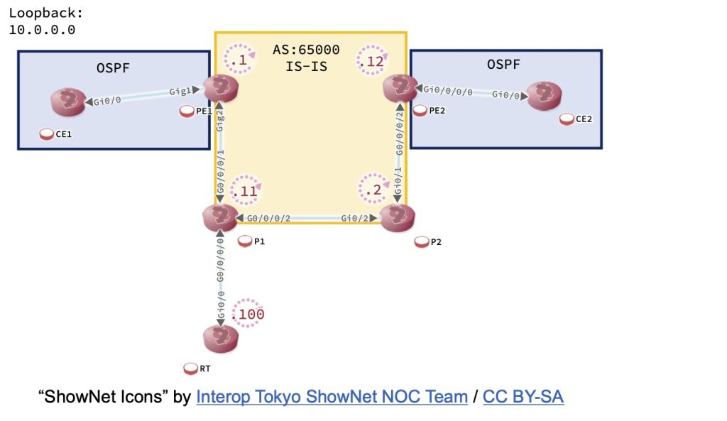
トポロジ図をまずみてみましょう。
CE1-CE2(OSPF)間に異なるIGP(IS-IS)が存在するので、再配送の可能性も考えてまずはIS-IS区間をみてみましょう。
PE1>sh ip ro | begin Gateway
Gateway of last resort is not set

      10.0.0.0/8 is variably subnetted, 3 subnets, 2 masks
C        10.0.0.1/32 is directly connected, Loopback0
C        10.1.11.0/24 is directly connected, GigabitEthernet2
L        10.1.11.1/32 is directly connected, GigabitEthernet2

RP/0/0/CPU0:P1#sh ip ro | begin Gateway
Sun Jan 23 12:13:38.204 UTC
Gateway of last resort is not set

C    10.0.0.0/24 is directly connected, 1d04h, Loopback0
L    10.0.0.11/32 is directly connected, 1d04h, Loopback0
S    10.0.0.100/32 [1/0] via 172.16.1.100, 1d04h
C    10.1.11.0/24 is directly connected, 1d04h, GigabitEthernet0/0/0/1
L    10.1.11.11/32 is directly connected, 1d04h, GigabitEthernet0/0/0/1
C    10.2.11.0/24 is directly connected, 1d04h, GigabitEthernet0/0/0/2
L    10.2.11.11/32 is directly connected, 1d04h, GigabitEthernet0/0/0/2
C    172.16.1.0/24 is directly connected, 1d04h, GigabitEthernet0/0/0/0
L    172.16.1.254/32 is directly connected, 1d04h, GigabitEthernet0/0/0/0

P2>sh ip ro | begin Gateway
Gateway of last resort is not set

      10.0.0.0/8 is variably subnetted, 6 subnets, 2 masks
C        10.0.0.0/24 is directly connected, Loopback0
L        10.0.0.2/32 is directly connected, Loopback0
C        10.2.11.0/24 is directly connected, GigabitEthernet0/2
L        10.2.11.2/32 is directly connected, GigabitEthernet0/2
C        10.2.12.0/24 is directly connected, GigabitEthernet0/1
L        10.2.12.2/32 is directly connected, GigabitEthernet0/1

RP/0/0/CPU0:PE2#sh ip ro | begin Gateway
Sun Jan 23 12:14:09.432 UTC
Gateway of last resort is not set

L    10.0.0.12/32 is directly connected, 1d04h, Loopback0
C    10.2.12.0/24 is directly connected, 1d04h, GigabitEthernet0/0/0/2
L    10.2.12.12/32 is directly connected, 1d04h, GigabitEthernet0/0/0/2
おや?IS-ISの経路情報が全くありません。ネイバ関係は確立できているのでしょうか?
PE1>show isis neighbors

Tag SP:
System Id       Type Interface     IP Address      State Holdtime Circuit Id

RP/0/0/CPU0:P1#show isis neighbors
Sun Jan 23 12:14:58.139 UTC

IS-IS SP neighbors:
System Id      Interface        SNPA           State Holdtime Type IETF-NSF

P2>show isis neighbors

Tag SP:
System Id       Type Interface     IP Address      State Holdtime Circuit Id

RP/0/0/CPU0:PE2#show isis neighbors
Sun Jan 23 12:15:01.949 UTC

IS-IS SP neighbors:
System Id      Interface        SNPA           State Holdtime Type IETF-NSF
確立できていません。まずはここからですね。とりあえずIS-ISのプロトコルレベルで情報収集してみましょう。
PE1>show isis protocol

Tag SP:
IS-IS Router: SP (0x10000)
  System Id: 0000.0000.0001.00  IS-Type: level-1
  Manual area address(es):
	49.0001
  Routing for area address(es):
	49.0001
  Interfaces supported by IS-IS:
	GigabitEthernet2 - IP
  Passive interface:
	Loopback0
  Redistribute:
    static (on by default)
    eBGP-neighbors
  Distance for L2 CLNS routes: 110
  RRR level: none
  Generate narrow metrics: level-1-2
  Accept narrow metrics:   level-1-2
  Generate wide metrics:   none
Accept wide metrics: nonePE1はGig2(P1接続インターフェース)とLoopback0でIS-ISが動作しており、エリア49.0001に所属していることがわかります。またIS-TypeはLevel-1で動作していることもわかります。
RP/0/0/CPU0:P1#show isis protocol
Sun Jan 23 12:17:UTC

IS-IS Router: SP
  System Id: 0000.0000.0011
  IS Levels: level-1
  Manual area address(es):
    49.0011
  Routing for area address(es):
    49.0011
  Non-stop forwarding: Disabled
  Most recent startup mode: Cold Restart
  Topologies supported by IS-IS:
    IPv4 Unicast
      Level-1
        Metric style (generate/accept): Narrow/Narrow
        Metric: 10
        ISPF status: Disabled
      Redistributing:
        Static
      Distance: 115
      Advertise Passive Interface Prefixes Only: No
  Interfaces supported by IS-IS:
    Loopback0 is running passively (passive in configuration)
    GigabitEthernet0/0/0/1 is running actively (active in configuration)
GigabitEthernet0/0/0/2 is running actively (active in configuration)P1はG0/0/0/1(PE1接続インターフェース)、G0/0/0/2(P2接続インターフェース)とLoopback0でIS-ISが動作しており、エリア49.0011に所属していることがわかります。またIS-TypeはLevel-1で動作していることもわかります。
P2>show isis protocol

Tag SP:
IS-IS Router: SP
  System Id: 0000.0000.0002.00  IS-Type: level-1
  Manual area address(es):
	49.0002
  Routing for area address(es):
	49.0002
  Interfaces supported by IS-IS:
	GigabitEthernet0/2 - IP
	GigabitEthernet0/1 - IP
	Loopback0 - IP
  Redistribute:
    static (on by default)
  Distance for L2 CLNS routes: 110
  RRR level: none
  Generate narrow metrics: level-1-2
  Accept narrow metrics:   level-1-2
  Generate wide metrics:   none
Accept wide metrics: noneP2はGig0/2(P1接続インターフェース)、G0/1(PE2接続インターフェース)とLoopback0でIS-ISが動作しており、エリア49.0002に所属していることがわかります。またIS-TypeはLevel-1で動作していることもわかります。
RP/0/0/CPU0:PE2#show isis protocol
Sun Jan 23 12:18:09.206 UTC

IS-IS Router: SP
  System Id: 0000.0000.0012
  IS Levels: level-1
  Manual area address(es):
    49.0012
  Routing for area address(es):
    49.0012
  Non-stop forwarding: Disabled
  Most recent startup mode: Cold Restart
  Topologies supported by IS-IS:
    IPv4 Unicast
      Level-1
        Metric style (generate/accept): Narrow/Narrow
        Metric: 10
        ISPF status: Disabled
      No protocols redistributed
      Distance: 115
      Advertise Passive Interface Prefixes Only: No
  Interfaces supported by IS-IS:
    Loopback0 is running passively (passive in configuration)
GigabitEthernet0/0/0/2 is running actively (active in configuration)PE2はG0/0/0/2(P2接続インターフェース)とLoopback0でIS-ISが動作しており、エリア49.0012に所属していることがわかります。またIS-TypeはLevel-1で動作していることもわかります。
ん?
IS-ISでは、Level-1ルータは同一エリア、Level-2ルータは異なるエリアを接続するルータです。Level-1ルータが異なるエリアに送信する場合には同一エリアに所属するL1-L2ルータをネクストホップとします。このことからすると、現在「すべてのルータが異なるエリアに属する」状況で「すべてのルータがLevel-1ルータ」となっているので、隣接関係が確立できません。
解決するには以下の2つが考えられます。
- すべてのルータをLevel-1/2もしくはLevel-2とし、異なるエリアでも隣接関係確立可能にする。
- すべてのルータをLevel-1のまま、同一エリアに所属させる。
今回の環境では規模も大きくないですし、全部同じエリアにしてみましょう。IS-ISでは、エリアは NET (NETWORK ENTITY TITLE)で設定します。NETは「エリア+システムID」で設定します。どれとも被らないように、49.0000 エリアにしてみましょう。
PE1>en
PE1#conf t
Enter configuration commands, one per line.  End with CNTL/Z.
PE1(config)#router isis SP
PE1(config-router)#net 49.0000.0000.0000.0001.00
PE1(config-router)#end

RP/0/0/CPU0:P1#conf
Sun Jan 23 12:48:44.100 UTC
RP/0/0/CPU0:P1(config)#router isis SP
RP/0/0/CPU0:P1(config-isis)#net 49.0000.0000.0000.0011.00
RP/0/0/CPU0:P1(config-isis)#commit
Sun Jan 23 12:49:20.958 UTC
RP/0/0/CPU0:P1(config-isis)#end

P2#conf t
Enter configuration commands, one per line.  End with CNTL/Z.
P2(config)#router isis SP
P2(config-router)#net 49.0000.0000.0000.0002.00
P2(config-router)#end

RP/0/0/CPU0:PE2#conf
Sun Jan 23 12:47:13.716 UTC
RP/0/0/CPU0:PE2(config)#router isis SP
RP/0/0/CPU0:PE2(config-isis)#net 49.0000.0000.0000.0012.00
RP/0/0/CPU0:PE2(config-isis)#commit
Sun Jan 23 12:49:31.257 UTC
RP/0/0/CPU0:PE2(config-isis)#end
では隣接関係を確認してみます。
PE1#show isis neighbors

Tag SP:
System Id       Type Interface     IP Address      State Holdtime Circuit Id
P1              L1   Gi2           10.1.11.11      UP    7        P1.01

RP/0/0/CPU0:P1#show isis neighbors
Sun Jan 23 12:50:22.283 UTC

IS-IS SP neighbors:
System Id      Interface        SNPA           State Holdtime Type IETF-NSF
PE1            Gi0/0/0/1        5000.0002.0001 Up    23       L1   Capable
P2             Gi0/0/0/2        5000.0004.0002 Up    26       L1   Capable

Total neighbor count: 2

P2#show isis neighbors

Tag SP:
System Id       Type Interface     IP Address      State Holdtime Circuit Id
P1              L1   Gi0/2         10.2.11.11      UP    8        P1.03
PE2             L1   Gi0/1         10.2.12.12      UP    8        PE2.01

RP/0/0/CPU0:PE2#show isis neighbors
Sun Jan 23 12:50:43.442 UTC

IS-IS SP neighbors:
System Id      Interface        SNPA           State Holdtime Type IETF-NSF
P2             Gi0/0/0/2        5000.0004.0001 Up    25       L1   Capable

Total neighbor count: 1
大丈夫そうですね。
MP-BGP
次に考えるところですが、期待されている出力はこうでした。
CE1#ping 192.168.200.200 so lo0
Type escape sequence to abort.
Sending 5, 100-byte ICMP Echos to 192.168.200.200, timeout is 2 seconds:
Packet sent with a source address of 192.168.100.100
!!!!!
Success rate is 100 percent (5/5), round-trip min/avg/max = 7/7/8 ms
CE1#trace 192.168.200.200 so lo0
Type escape sequence to abort.
Tracing the route to 192.168.200.200
VRF info: (vrf in name/id, vrf out name/id)
  1 192.168.1.254 1 msec 1 msec 1 msec
  2 192.168.2.254 [MPLS: Label 24001 Exp 0] 10 msec 7 msec 7 msec
  3 192.168.2.2 7 msec *  9 msec


CE2#ping 192.168.100.100 so lo0
Type escape sequence to abort.
Sending 5, 100-byte ICMP Echos to 192.168.100.100, timeout is 2 seconds:
Packet sent with a source address of 192.168.200.200
!!!!!
Success rate is 100 percent (5/5), round-trip min/avg/max = 7/7/8 ms
CE2#trace 192.168.100.100 so lo0
Type escape sequence to abort.
Tracing the route to 192.168.100.100
VRF info: (vrf in name/id, vrf out name/id)
  1 192.168.2.254 2 msec 2 msec 2 msec
  2 192.168.1.254 [MPLS: Label 17 Exp 0] 6 msec 5 msec 6 msec
  3 192.168.1.1 7 msec *  7 msec
CE1-CE2間は5ホップあるはずなのに3ホップしかありません。しかも間にMPLSラベルの情報も見えます。これはもしかするとMPLSを使ったL3VPN(MPLS-VPN)環境なのかもしれません。もしMPLSであれば、IS-ISの範囲はMPLSラベルスイッチングがされていると予想できます。ちょっと確認してみましょう。
PE1#show mpls interfaces
Interface              IP            Tunnel   BGP Static Operational
GigabitEthernet2       Yes (ldp)     No       No  No     Yes

RP/0/0/CPU0:P1#show mpls interfaces
Wed Jan 26 12:18:50.537 UTC
Interface                  LDP      Tunnel   Static   Enabled
-------------------------- -------- -------- -------- --------
GigabitEthernet0/0/0/1     Yes      No       No       Yes
GigabitEthernet0/0/0/2     Yes      No       No       Yes

P2#show mpls interfaces
Interface              IP            Tunnel   BGP Static Operational
GigabitEthernet0/1     Yes (ldp)     No       No  No     Yes
GigabitEthernet0/2     Yes (ldp)     No       No  No     Yes

RP/0/0/CPU0:PE2#show mpls interfaces
Wed Jan 26 12:18:54.156 UTC
Interface                  LDP      Tunnel   Static   Enabled
-------------------------- -------- -------- -------- --------
GigabitEthernet0/0/0/2     Yes      No       No       Yes
IS-IS区間のインターフェースでMPLSが有効になっているのが確認できました。
MPLSでは転送時に宛先IPアドレスに対応するラベルを使って出力インターフェースを決定します。では宛先となる192.168.100.100/32や192.168.200.200/32のラベル情報はあるでしょうか?
PE1#show mpls forwarding-table
Local      Outgoing   Prefix           Bytes Label   Outgoing   Next Hop
Label      Label      or Tunnel Id     Switched      interface
16         No Label   192.168.1.0/24[V]   \
                                       0             aggregate/VPN
17         No Label   192.168.100.100/32[V]   \
                                       0             Gi1        192.168.1.1
18         24000      10.0.0.100/32    0             Gi2        10.1.11.11
19         24003      10.0.0.12/32     0             Gi2        10.1.11.11
20         Pop Label  10.0.0.0/24      0             Gi2        10.1.11.11
21         Pop Label  10.2.11.0/24     0             Gi2        10.1.11.11
22         24001      10.2.12.0/24     0             Gi2        10.1.11.11

RP/0/0/CPU0:P1#show mpls forwarding
Wed Jan 26 12:23:31.107 UTC
Local  Outgoing    Prefix             Outgoing     Next Hop        Bytes
Label  Label       or ID              Interface                    Switched
------ ----------- ------------------ ------------ --------------- ------------
24000  Unlabelled  10.0.0.100/32      Gi0/0/0/0    172.16.1.100    2015364
24001  Unlabelled  10.2.12.0/24       Gi0/0/0/2    10.2.11.2       0
24002  Pop         10.0.0.1/32        Gi0/0/0/1    10.1.11.1       480282
24003  Unlabelled  10.0.0.12/32       Gi0/0/0/2    10.2.11.2       0

P2#show mpls forwarding-table
Local      Outgoing   Prefix           Bytes Label   Outgoing   Next Hop
Label      Label      or Tunnel Id     Switched      interface
16         No Label   10.0.0.100/32    1051148       Gi0/2      10.2.11.11
17         Pop Label  10.0.0.12/32     0             Gi0/1      10.2.12.12
18         No Label   10.0.0.1/32      0             Gi0/2      10.2.11.11
19         No Label   10.1.11.0/24     0             Gi0/2      10.2.11.11

RP/0/0/CPU0:PE2#show mpls forwarding
Wed Jan 26 12:23:45.836 UTC
Local  Outgoing    Prefix             Outgoing     Next Hop        Bytes
Label  Label       or ID              Interface                    Switched
------ ----------- ------------------ ------------ --------------- ------------
24000  Aggregate   VPN: Per-VRF Aggr[V]   \
                                      VPN                          0
24001  Unlabelled  192.168.200.200/32[V]   \
                                      Gi0/0/0/0    192.168.2.2     0
24002  Pop         10.2.11.0/24       Gi0/0/0/2    10.2.12.2       0
24003  Pop         10.0.0.0/24        Gi0/0/0/2    10.2.12.2       480152
24004  16          10.0.0.100/32      Gi0/0/0/2    10.2.12.2       881608
24005  19          10.1.11.0/24       Gi0/0/0/2    10.2.12.2       0
24006  18          10.0.0.1/32        Gi0/0/0/2    10.2.12.2       0
両端のPE1, PE2にはそれらしいものがありますが、相手側の情報が見えていません。具体的には、PE1に192.168.200.200/32、PE2に192.168.100.100/32の情報がなければ転送することができません。
MPLS-L3VPNでは、BGPの拡張であるMulti-Protocol BGP(MP-BGP)によって「VPN識別ラベル」を交換し、そのVPNの出口となるルータまでの転送用に「転送ラベル」を使用します。詳しくはこちらのPDFをご覧ください。
現在の状況からすると、この「VPN識別ラベル」の情報が両端に存在しないので、MP-BGPに問題があると推測されます。PE1, PE2でのMP-BGPの状態を確認してみます。MPLS-L3VPNでVPN識別ラベルを交換する際はVPNv4アドレスファミリを使用するので、showコマンドでもvpnv4アドレスファミリを指定します。
PE1#show bgp vpnv4 unicast all summary | begin Neighbor
Neighbor        V           AS MsgRcvd MsgSent   TblVer  InQ OutQ Up/Down  State/PfxRcd
10.0.0.100      4        65000       0       0        1    0    0 never    Active

RP/0/0/CPU0:PE2#show bgp vpnv4 unicast summary | begin Neighbor
Wed Jan 26 12:38:22.696 UTC
Neighbor        Spk    AS MsgRcvd MsgSent   TblVer  InQ OutQ  Up/Down  St/PfxRcd
10.0.0.100 0 65000 0 0 0 0 0 00:00:00 Activeおや?互いにピアリングしているのではなく、10.0.0.100 とピアリングするようになっているようです。しかしそのルータとは接続できていないようです。10.0.0.100はトポロジからするとRTルータのようです。
ではRTルータのBGP接続はどうなっているのでしょうか?
RT>show bgp vpnv4 unicast all summary | begin Neighbor
Neighbor        V           AS MsgRcvd MsgSent   TblVer  InQ OutQ Up/Down  State/PfxRcd
10.0.0.1        4        65000       0       0        1    0    0 never    Idle
10.0.0.12       4        65000       0       0        1    0    0 never    Idle
RT>ping 10.0.0.1
Type escape sequence to abort.
Sending 5, 100-byte ICMP Echos to 10.0.0.1, timeout is 2 seconds:
.....
Success rate is 0 percent (0/5)
RT>ping 10.0.0.12
Type escape sequence to abort.
Sending 5, 100-byte ICMP Echos to 10.0.0.12, timeout is 2 seconds:
.....
Success rate is 0 percent (0/5)
こちらもピアリングができておらず、しかも疎通できていません。念のためルーティングテーブルもみてみます。
RT>show ip route | begin Gateway
Gateway of last resort is not set

      10.0.0.0/32 is subnetted, 1 subnets
C        10.0.0.100 is directly connected, Loopback0
      172.16.0.0/16 is variably subnetted, 2 subnets, 2 masks
C        172.16.1.0/24 is directly connected, GigabitEthernet0/0
L        172.16.1.100/32 is directly connected, GigabitEthernet0/0
RT>show ip protocols
*** IP Routing is NSF aware ***

Routing Protocol is "application"
  Sending updates every 0 seconds
  Invalid after 0 seconds, hold down 0, flushed after 0
  Outgoing update filter list for all interfaces is not set
  Incoming update filter list for all interfaces is not set
  Maximum path: 32
  Routing for Networks:
  Routing Information Sources:
    Gateway         Distance      Last Update
  Distance: (default is 4)

Routing Protocol is "bgp 65000"
  Outgoing update filter list for all interfaces is not set
  Incoming update filter list for all interfaces is not set
  Route Reflector for address family VPNv4 Unicast, 2 clients
  IGP synchronization is disabled
  Automatic route summarization is disabled
  Maximum path: 1
  Routing Information Sources:
    Gateway         Distance      Last Update
  Distance: external 20 internal 200 local 200
経路情報がありません。また、ルーティングプロトコルはBGP以外動作していないようなので、このままではPE1, PE2とピアリングすることはできません。トポロジ図からみても、RTルータはIS-ISに含まれていないので、勝手にIS-ISを有効化して良いか判断がつきません。何か手がないか、設問をもう一度見てみます。
条件
- 各インターフェースのIPアドレスは変更してはならない
- 既存の設定内容は削除してはならない
- トンネリング、ルーティング追加は許可しない。ただし、必要な場合に限り1箇所だけスタティックルートの追加を認める。
1箇所だけスタティックルートの追加が可能なので、ここで使ってみることにします。RTルータはP1にしか接続していないので、デフォルトルートを追加してみましょう。
RP/0/0/CPU0:P1#show ipv4 interface brief
Wed Jan 26 12:54:59.238 UTC

Interface                      IP-Address      Status          Protocol Vrf-Name
Loopback0                      10.0.0.11       Up              Up       default
MgmtEth0/0/CPU0/0              unassigned      Shutdown        Down     default
GigabitEthernet0/0/0/0         172.16.1.254    Up              Up       default ←対抗アドレスはこれ
GigabitEthernet0/0/0/1         10.1.11.11      Up              Up       default
GigabitEthernet0/0/0/2         10.2.11.11      Up              Up       default

RT>en
RT#conf t
Enter configuration commands, one per line.  End with CNTL/Z.
RT(config)#ip route 0.0.0.0 0.0.0.0 172.16.1.254
RT(config)#end
RT#
*Jan 26 12:58:58.337: %SYS-5-CONFIG_I: Configured from console by console
RT#
*Jan 26 12:59:01.663: %BGP-5-ADJCHANGE: neighbor 10.0.0.1 Up
RT#
*Jan 26 12:59:11.689: %BGP-5-ADJCHANGE: neighbor 10.0.0.12 Up
ピアリングできたようです。ということはRTルータへの到達性は元々PE1, PE2にあったのでしょうか?
PE1#show ip route isis | begin Gateway
Gateway of last resort is not set

      10.0.0.0/8 is variably subnetted, 9 subnets, 2 masks
i L1     10.0.0.0/24 [115/30] via 10.1.11.11, 09:00:57, GigabitEthernet2
i L1     10.0.0.11/32 [115/10] via 10.1.11.11, 09:00:57, GigabitEthernet2
i L1     10.0.0.12/32 [115/30] via 10.1.11.11, 3d10h, GigabitEthernet2
i L1     10.0.0.100/32 [115/10] via 10.1.11.11, 3d10h, GigabitEthernet2
i L1     10.2.11.0/24 [115/20] via 10.1.11.11, 3d10h, GigabitEthernet2
i L1     10.2.12.0/24 [115/30] via 10.1.11.11, 3d10h, GigabitEthernet2
PE1#show ip route 10.0.0.100
Routing entry for 10.0.0.100/32
  Known via "isis", distance 115, metric 10, type level-1
  Redistributing via isis SP ←ここ
  Last update from 10.1.11.11 on GigabitEthernet2, 3d10h ago
  Routing Descriptor Blocks:
  * 10.1.11.11, from 10.0.0.11, 3d10h ago, via GigabitEthernet2
      Route metric is 10, traffic share count is 1
どうやらIS-ISに再配送がかかっているようです。この経路を知っていそうなのは接続しているP1なので、本当に再配送されているのか念のため確認しておきましょう。
RP/0/0/CPU0:P1#sh run router isis
Wed Jan 26 23:39:13.520 UTC
router isis SP
 is-type level-1
 net 49.0000.0000.0000.0011.00
 net 49.0011.0000.0000.0011.00
 address-family ipv4 unicast
  redistribute static level-1
  mpls ldp auto-config
 !
 interface Loopback0
  passive
  address-family ipv4 unicast
  !
 !
 interface GigabitEthernet0/0/0/1
  address-family ipv4 unicast
  !
 !
 interface GigabitEthernet0/0/0/2
  address-family ipv4 unicast
  !
 !
!

RP/0/0/CPU0:P1#sh run router static
Wed Jan 26 23:39:16.710 UTC
router static
 address-family ipv4 unicast
  10.0.0.100/32 172.16.1.100
 !
!
P1のIS-IS IPv4アドレスファミリ内でスタティック経路をlevel-1として再配送する設定が入っており、スタティック経路の設定としてちゃんとRTルータ(10.0.0.100/32)の経路も入っていました。これがすぐにピアが確立した理由ですね。
前述の通り、IS-ISの障害(エリアミスマッチ)には2つの解法がありましたが、is-type を元々のlevel-1からlevel-2に変更した場合はこの再配送にも設定変更が必要になります。
ではMP-BGPの状態を確認してみましょう。
RT#show bgp vpnv4 unicast all summary | begin Neighbor
Neighbor        V           AS MsgRcvd MsgSent   TblVer  InQ OutQ Up/Down  State/PfxRcd
10.0.0.1        4        65000       9       9        5    0    0 00:03:18        2
10.0.0.12       4        65000       8      11        5    0    0 00:03:08        2

PE1#show bgp vpnv4 unicast all summary | begin Neighbor
Neighbor        V           AS MsgRcvd MsgSent   TblVer  InQ OutQ Up/Down  State/PfxRcd
10.0.0.100      4        65000       8       9        3    0    0 00:02:53        0

RP/0/0/CPU0:PE2#show bgp vpnv4 unicast summary | begin Neighbor
Wed Jan 26 13:02:54.075 UTC
Neighbor        Spk    AS MsgRcvd MsgSent   TblVer  InQ OutQ  Up/Down  St/PfxRcd
10.0.0.100        0 65000      12       9        8    0    0 00:04:25          0
RTルータはプレフィックスを受信しているのに、PE1, PE2は受信できていません。何かフィルタがあるのでしょうか?
PE1#show access-list
Extended IP access list meraki-fqdn-dns
PE1#show route-map
PE1#

RP/0/0/CPU0:PE2#show rpl
Wed Jan 26 13:03:59.601 UTC
% No such configuration item(s)

RP/0/0/CPU0:PE2#show access-lists
Wed Jan 26 13:04:05.271 UTC

RT#show access-list
RT#show route-map
RT#
何もありません。うーん、ではRTはどうして受信できているのでしょうか?
Route-Target
RTルータが受け取っている情報を見てみます。
RT#show bgp vpnv4 unicast all
BGP table version is 5, local router ID is 10.0.0.100
Status codes: s suppressed, d damped, h history, * valid, > best, i - internal,
              r RIB-failure, S Stale, m multipath, b backup-path, f RT-Filter,
              x best-external, a additional-path, c RIB-compressed,
Origin codes: i - IGP, e - EGP, ? - incomplete
RPKI validation codes: V valid, I invalid, N Not found

     Network          Next Hop            Metric LocPrf Weight Path
Route Distinguisher: 65000:1
 *>i 192.168.1.0      10.0.0.1                 0    100      0 ?
 *>i 192.168.100.100/32
                       10.0.0.1                 2    100      0 ?
Route Distinguisher: 65000:2
 *>i 192.168.2.0      10.0.0.12                0    100      0 ?
 *>i 192.168.200.200/32
                       10.0.0.12                2    100      0 ?
RT#show bgp vpnv4 unicast all 192.168.100.100/32
BGP routing table entry for 65000:1:192.168.100.100/32, version 2
Paths: (1 available, best #1, no table)
  Advertised to update-groups:
     1
  Refresh Epoch 1
  Local, (Received from a RR-client)
    10.0.0.1 (via default) from 10.0.0.1 (10.0.0.1)
      Origin incomplete, metric 2, localpref 100, valid, internal, best
      Extended Community: RT:65000:1 OSPF DOMAIN ID:0x0005:0x000000010200
        OSPF RT:0.0.0.1:2:0 OSPF ROUTER ID:192.168.1.254:0
      mpls labels in/out nolabel/17
      rx pathid: 0, tx pathid: 0x0
RT#show bgp vpnv4 unicast all 192.168.200.200/32
BGP routing table entry for 65000:2:192.168.200.200/32, version 4
Paths: (1 available, best #1, no table)
  Advertised to update-groups:
     1
  Refresh Epoch 1
  Local, (Received from a RR-client)
    10.0.0.12 (via default) from 10.0.0.12 (10.0.0.12)
      Origin incomplete, metric 2, localpref 100, valid, internal, best
      Extended Community: RT:65000:1 OSPF RT:0.0.0.2:1:0
        OSPF ROUTER ID:10.0.0.12:0
      mpls labels in/out nolabel/24001
rx pathid: 0, tx pathid: 0x0期待している通り、192.168.100.100/32 は10.0.0.1(PE1)に、192.168.200.200/32 は10.0.0.12(PE2)に向かいそうに見えます。
おっと、ここでもう1つ確認できるものを見つけました。各プレフィックスについているExtended CommunityであるRT(Route Target)です。MP-BGPでVPNv4プレフィックスを受信するには、このRTの値がVPNの情報とマッチしている必要があります。VPNはVRF(Virtual Routing and Forwarding)によって設定されるのでこちらをみてみます。
PE1#show vrf detail
VRF VPN (VRF Id = 1); default RD 65000:1; default VPNID <not set>
  New CLI format, supports multiple address-families
  Flags: 0x180C
  Interfaces:
    Gi1
Address family ipv4 unicast (Table ID = 0x1):
  Flags: 0x0
  Export VPN route-target communities
    RT:65000:1 ←ここ
  Import VPN route-target communities
    RT:65000:2 ←ここ
  No import route-map
  No global export route-map
  No export route-map
  VRF label distribution protocol: not configured
  VRF label allocation mode: per-prefix
Address family ipv6 unicast not active
Address family ipv4 multicast not active
Address family ipv6 multicast not activePE1はRTを65000:1として広告し、65000:2のものを取り込む設定になっています。
RP/0/0/CPU0:PE2#show vrf all detail
Wed Jan 26 13:15:01.416 UTC

VRF VPN; RD 65000:2; VPN ID not set
VRF mode: Regular
Description not set
Interfaces:
  GigabitEthernet0/0/0/0
Address family IPV4 Unicast
  Import VPN route-target communities:
    RT:65000:2 ←ここ
  Export VPN route-target communities:
    RT:65000:1 ←ここ
  No import route policy
  No export route policy
Address family IPV6 Unicast
  No import VPN route-target communities
  No export VPN route-target communities
  No import route policy
No export route policyPE1はRTを65000:1として広告し、65000:2のものを取り込む設定になっています。
RT#show bgp vpnv4 unicast all 192.168.100.100/32 | include RT
      Extended Community: RT:65000:1 OSPF DOMAIN ID:0x0005:0x000000010200
        OSPF RT:0.0.0.1:2:0 OSPF ROUTER ID:192.168.1.254:0
RT#show bgp vpnv4 unicast all 192.168.200.200/32 | include RT
      Extended Community: RT:65000:1 OSPF RT:0.0.0.2:1:0
192.168.100.100/32 にはRTとして65000:1、192.168.200.200/32 にもRTとして65000:1がついています。
ん?
VRFの設定では、取り込むRTがPE1, PE2どちらも「65000:2」となっているのに、お互いが広告しているプレフィックスには「65000:1」がついています。これではどちらも相手が広告したプレフィックスを取り込むことができません。同じVPNですので、どちらも「65000:1」のRTを取り込めるようにしてみます。
PE1#show run vrf VPN
Building configuration...

Current configuration : 466 bytes
vrf definition VPN
 rd 65000:1
 !
 address-family ipv4
  route-target export 65000:1
  route-target import 65000:2
 exit-address-family
(略)
PE1#conf t
Enter configuration commands, one per line.  End with CNTL/Z.
PE1(config)#vrf definition VPN
PE1(config-vrf)#address-family ipv4
PE1(config-vrf-af)#route-target import 65000:1
PE1(config-vrf-af)#end

RP/0/0/CPU0:PE2#show run vrf VPN
Wed Jan 26 13:27:03.806 UTC
vrf VPN
 address-family ipv4 unicast
  import route-target
   65000:2
  !
  export route-target
   65000:1
  !
 !
!

RP/0/0/CPU0:PE2#conf
Wed Jan 26 13:29:25.436 UTC
RP/0/0/CPU0:PE2(config)#vrf VPN
RP/0/0/CPU0:PE2(config-vrf)#address-family ipv4 unicast
RP/0/0/CPU0:PE2(config-vrf-af)#import route-target 65000:1
RP/0/0/CPU0:PE2(config-vrf-af)#commit
Wed Jan 26 13:29:43.185 UTC
RP/0/0/CPU0:PE2(config-vrf-af)#end
結果も良さそうです。
PE1#show bgp vpnv4 unicast all summary | begin Neighbor
Neighbor        V           AS MsgRcvd MsgSent   TblVer  InQ OutQ Up/Down  State/PfxRcd
10.0.0.100      4        65000      47      42        7    0    0 00:33:17        2

RP/0/0/CPU0:PE2#show bgp vpnv4 unicast summary | begin Neighbor
Wed Jan 26 13:30:40.381 UTC
Neighbor        Spk    AS MsgRcvd MsgSent   TblVer  InQ OutQ  Up/Down  St/PfxRcd
10.0.0.100        0 65000      46      38       12    0    0 00:32:12          2
CEルータはどうでしょう?
CE1#show ip route 192.168.200.200
Routing entry for 192.168.200.200/32
  Known via "ospf 1", distance 110, metric 2
  Tag Complete, Path Length == 1, AS 65000, , type extern 2, forward metric 1
  Last update from 192.168.1.254 on GigabitEthernet0/0, 00:04:02 ago
  Routing Descriptor Blocks:
  * 192.168.1.254, from 192.168.1.254, 00:04:02 ago, via GigabitEthernet0/0
      Route metric is 2, traffic share count is 1
      Route tag 3489725928

CE2#show ip route 192.168.100.100
Routing entry for 192.168.100.100/32
  Known via "ospf 1", distance 110, metric 2
  Tag Complete, Path Length == 1, AS 65000, , type extern 2, forward metric 1
  Last update from 192.168.2.254 on GigabitEthernet0/0, 00:03:54 ago
  Routing Descriptor Blocks:
  * 192.168.2.254, from 10.0.0.12, 00:03:54 ago, via GigabitEthernet0/0
      Route metric is 2, traffic share count is 1
      Route tag 3489725928
対向ルータの経路情報が見えました!これで行けるか…?
CE1#trace 192.168.200.200 so lo0
Type escape sequence to abort.
Tracing the route to 192.168.200.200
VRF info: (vrf in name/id, vrf out name/id)
  1 192.168.1.254 2 msec 1 msec 1 msec
  2  *  *  *
  3  *  *  *
  4  *  *  *
  5  *  *  *
  6  *  *  *
  7  *  *  *
  8  *

CE2#trace 192.168.100.100 so lo0
Type escape sequence to abort.
Tracing the route to 192.168.100.100
VRF info: (vrf in name/id, vrf out name/id)
  1 192.168.2.254 5 msec 2 msec 2 msec
  2  *  *  *
  3  *  *  *
  4  *  *  *
  5  *  *  *
  6  *  *  *
  7  *  *  *
  8  *  *  *
まだダメみたいです。他に何があるのでしょうか?
VPN識別ラベルと転送ラベル
先ほどMPLS-L3VPNではVPN識別ラベルと転送ラベルを使うという話がありました。これは「あるVPNの特定のプレフィックスを表すラベル」と「VPNの端点となるルータへ到達するためのラベル」のことです。MPLS区間では、プレフィックスやVPN識別ラベルではなく「転送ラベル」を使うので、きちんとルータ間でMPLSラベルによる転送ができるのか確認してみます。PE1から見てみましょう。
PE1#show ip route vrf VPN 192.168.200.200

Routing Table: VPN
Routing entry for 192.168.200.200/32
  Known via "bgp 65000", distance 200, metric 2, type internal
  Redistributing via ospf 1
  Advertised by ospf 1 subnets
  Last update from 10.0.0.12 00:19:31 ago
  Routing Descriptor Blocks:
  * 10.0.0.12 (default), from 10.0.0.100, 00:19:31 ago
      Route metric is 2, traffic share count is 1
      AS Hops 0
      MPLS label: 24001
      MPLS Flags: MPLS Required
PE1は、192.168.200.200/32のラベル(VPN識別ラベル)を24001、ネクストホップ(VPNの対向ルータ)が10.0.0.12であると理解しています。ですので、10.0.0.12についてのラベルによる転送を確認していくことになります。
PE1#show mpls forwarding-table 10.0.0.12
Local      Outgoing   Prefix           Bytes Label   Outgoing   Next Hop
Label      Label      or Tunnel Id     Switched      interface
19         24003      10.0.0.12/32     0             Gi2        10.1.11.11
PE1はGi2インターフェースから転送ラベル24003をつけて10.1.11.11(P1)に渡します。
RP/0/0/CPU0:P1#show mpls forwarding
Wed Jan 26 14:30:23.296 UTC
Local  Outgoing    Prefix             Outgoing     Next Hop        Byte
Label  Label       or ID              Interface                    Switched
------ ----------- ------------------ ------------ --------------- ------------
24000  Unlabelled  10.0.0.100/32      Gi0/0/0/0    172.16.1.100    2053022
24001  Unlabelled  10.2.12.0/24       Gi0/0/0/2    10.2.11.2       0
24002  Pop         10.0.0.1/32        Gi0/0/0/1    10.1.11.1       844
24003  Unlabelled  10.0.0.12/32       Gi0/0/0/2    10.2.11.2       515 ←ここ
P1はラベル24003で受け取ったらGi0/0/0/2からラベルなしで10.2.11.2へ渡します。
P2#show mpls forwarding-table 10.0.0.12
Local      Outgoing   Prefix           Bytes Label   Outgoing   Next Hop
Label      Label      or Tunnel Id     Switched      interface
17         Pop Label  10.0.0.12/32     0             Gi0/1      10.2.12.12
P2は10.0.0.12/32へはGi0/1インターフェースから転送ラベルを取り外して(Pop Label)10.2.12.12(PE2)に渡すことになっています。
RP/0/0/CPU0:PE2#show mpls forwarding
Wed Jan 26 14:33:51.422 UTC
Local  Outgoing    Prefix             Outgoing     Next Hop        Bytes
Label  Label       or ID              Interface                    Switched
------ ----------- ------------------ ------------ --------------- ------------
24000  Aggregate   VPN: Per-VRF Aggr[V]   \
                                      VPN                          0
24001  Unlabelled  192.168.200.200/32[V]   \
                                      Gi0/0/0/0    192.168.2.2     300
24002  Pop         10.2.11.0/24       Gi0/0/0/2    10.2.12.2       0
24003  Pop         10.0.0.0/24        Gi0/0/0/2    10.2.12.2       588
24004  16          10.0.0.100/32      Gi0/0/0/2    10.2.12.2       535
24005  19          10.1.11.0/24       Gi0/0/0/2    10.2.12.2       0
24006  18          10.0.0.1/32        Gi0/0/0/2    10.2.12.2       0
PE2は転送ラベルを取り外した状態で受け取り、VPN識別ラベルである24001が見えるようになります。24001のラベルがついたパケットはラベルなしでGi0/0/0/0から192.168.2.2(CE2)に渡すことになっています。
このことからすると、本来PE1-PE2間はMPLSラベルによる転送パス(LSP: Label Swithing Path)が出来上がっているはずなのに、途中(P1-P2間)でラベルの情報が途切れているためLSPが確立していません。何かここに問題がありそうです。
MPLSでは隣接するルータとラベル情報をLDP(Label Distribution Protocol)によって交換しています。LDPででのネイバ確立ができているか確認してみましょう。
PE1#show mpls ldp neighbor | include Pee
Peer LDP Ident: 10.0.0.11:0; Local LDP Ident 10.0.0.1:0
RP/0/0/CPU0:P1#show mpls ldp neighbor | include Peer
Thu Jan 27 08:22:29.167 UTC
Peer LDP Identifier: 10.0.0.1:0
P2#show mpls ldp neighbor | include Peer
Peer LDP Ident: 10.0.0.12:0; Local LDP Ident 10.0.0.2:0
RP/0/0/CPU0:PE2#show mpls ldp neighbor | include Peer
Thu Jan 27 08:22:56.175 UTC
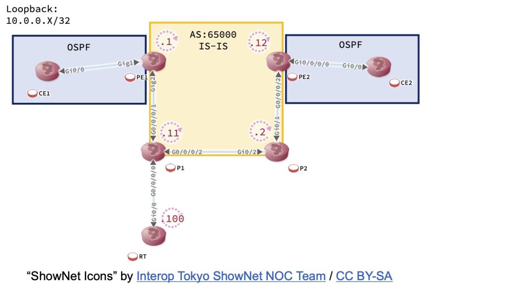
Peer LDP Identifier: 10.0.0.2:0おや?本来P1, P2間でもLDPネイバーが確立しているはずなのにできていません。LDPはLDPルータIDを使ってネイバ確立しますが、そのルータIDは「/32」であることが条件になっています。/32というとLooback0に割り当てているはずなので確認してみましょう。
RP/0/0/CPU0:P1#show run interface lo0
Wed Jan 26 14:18:16.486 UTC
interface Loopback0
 ipv4 address 10.0.0.11 255.255.255.0
!

P2#show run int lo0
Building configuration...

Current configuration : 81 bytes
!
interface Loopback0
 ip address 10.0.0.2 255.255.255.0
 ip router isis SP
end
なんとLoopback0が/24になっています。これがP1, P2間のLDPネイバ確立を妨げている原因のようです。Loopback0には/32のアドレスを割り当てる必要がありますので、ここを修正してみましょう。
RP/0/0/CPU0:P1#conf
Wed Jan 26 14:21:28.283 UTC
RP/0/0/CPU0:P1(config)#interface lo0
RP/0/0/CPU0:P1(config-if)#ipv4 address 10.0.0.11/32
RP/0/0/CPU0:P1(config-if)#commit
Wed Jan 26 14:22:04.920 UTC
RP/0/0/CPU0:P1(config-if)#end

P2#conf t
Enter configuration commands, one per line.  End with CNTL/Z.
P2(config)#int lo0
P2(config-if)#ip addr 10.0.0.2 255.255.255.255
P2(config-if)#end
さて、LDPピアリングはどうなったでしょう?
RP/0/0/CPU0:P1#show mpls ldp neighbor | include Peer
Thu Jan 27 08:30:12.225 UTC
Peer LDP Identifier: 10.0.0.1:0
Peer LDP Identifier: 10.0.0.2:0

P2#show mpls ldp neighbor | include Peer
    Peer LDP Ident: 10.0.0.12:0; Local LDP Ident 10.0.0.2:0
    Peer LDP Ident: 10.0.0.11:0; Local LDP Ident 10.0.0.2:0
ネイバ確立しました。これでLSPも確立したはずです。確認しましょう。
PE1#show mpls forwarding-table 10.0.0.12
Local      Outgoing   Prefix           Bytes Label   Outgoing   Next Hop
Label      Label      or Tunnel Id     Switched      interface
22         24003      10.0.0.12/32     0             Gi2        10.1.11.11

RP/0/0/CPU0:P1#show mpls forwarding labels 24003
Thu Jan 27 08:31:58.538 UTC
Local  Outgoing    Prefix             Outgoing     Next Hop        Bytes
Label  Label       or ID              Interface                    Switched
------ ----------- ------------------ ------------ --------------- ------------
24003  19          10.0.0.12/32       Gi0/0/0/2    10.2.11.2       226

P2#show mpls forwarding-table labels 19
Local      Outgoing   Prefix           Bytes Label   Outgoing   Next Hop
Label      Label      or Tunnel Id     Switched      interface
19         Pop Label  10.0.0.12/32     9328          Gi0/1      10.2.12.12
PE1から10.0.0.12へは「転送ラベルとして24003をセット→19に付け替え→転送ラベルを外してPE2に渡す」ようになってますね。疎通確認してみましょう。
CE1#trace 192.168.200.200 so lo0
Type escape sequence to abort.
Tracing the route to 192.168.200.200
VRF info: (vrf in name/id, vrf out name/id)
  1 192.168.1.254 2 msec 1 msec 1 msec
  2 192.168.2.254 [MPLS: Label 24001 Exp 0] 15 msec 7 msec 8 msec
  3 192.168.2.2 7 msec *  9 msec

CE2#trace 192.168.100.100 so lo0
Type escape sequence to abort.
Tracing the route to 192.168.100.100
VRF info: (vrf in name/id, vrf out name/id)
  1 192.168.2.254 2 msec 2 msec 1 msec
  2 192.168.1.254 [MPLS: Label 17 Exp 0] 9 msec 7 msec 8 msec
  3 192.168.1.1 7 msec *  8 msec
通るようになりました!これで解決ですね。
回答例
かなり長くなってしまいました。それではNETCONの回答形式である報告書っぽくしてみましょう。
トラブル事象について調査、対応致しましたので報告いたします。
- IS-IS区間でのエリアIDミスマッチ
原因)IS-IS区間の各ルータにおいて、全てがLevel-1ルータにもかかわらずエリアIDが不一致であったために経路情報が交換できていませんでした。
対処)各ルータに同一エリアとなるNET設定を追加しました。 - RTルータの経路情報不足によるMP-BGPピアリング確立不可
原因)IS-IS区間外のRTルータがPE1, PE2ルータのMP-BGPピアリング先になっていますが、RTルータからPE1, PE2ルータへの到達性がないため、MP-BGPピアリングが確立できていませんでした。
対処)RTルータにP1をネクストホップとしたデフォルトルート(ip route 0.0.0.0 0.0.0.0 172.16.1.254)を追加しました。 - VPNのインポート対象route-target不正
原因)PE1, PE2ルータ双方で、広告するプレフィックスのroute-targetを65000:2としていますが、インポート対象のroute-targetが65000:1となっているため、VPN対象プレフィックスが取り込めていませんでした。
対処)PE1, PE2ルータ双方に65000:1のroute-targetを取り込む設定を追加しました。 - LSP確立不可
原因)PE1-PE2間のルータのLoopback0インターフェースのプレフィックス長が/32になっていないため、PE1-PE2間のLSPが確立していませんでした。
対処)P1ルータのLoopback0において、プレフィックス長を/24から/32に修正しました。
以上
まとめ
MPLS-L3VPNって、アンダーレイのIGP、データプレーンのMPLS、オーバーレイのMP-BGPそれぞれがきちんと動作していないといけない、なかなか複雑なVPNです。単にshow running-configしても問題点が見つけにくいものという狙いで作成した問題です。どれだけの方が正答できたのかな。
コンフィグ
CE1
hostname CE1
!
boot-start-marker
boot-end-marker
!
!
!
no aaa new-model
ethernet lmi ce
!
!
!
mmi polling-interval 60
no mmi auto-configure
no mmi pvc
mmi snmp-timeout 180
!
!
!
!
!
!
!
!
!
!
!
no ip domain lookup
ip cef
no ipv6 cef
!
multilink bundle-name authenticated
!
!
!
!
!
redundancy
!
no cdp run
!
!
!
!
!
!
!
!
!
!
!
!
!
!
interface Loopback0
 no shutdown
 ip address 192.168.100.100 255.255.255.255
!
interface GigabitEthernet0/0
 no shutdown
 ip address 192.168.1.1 255.255.255.0
 duplex auto
 speed auto
 media-type rj45
 no cdp enable
!
interface GigabitEthernet0/1
 no shutdown
 no ip address
 shutdown
 duplex auto
 speed auto
 media-type rj45
 no cdp enable
!
interface GigabitEthernet0/2
 no shutdown
 no ip address
 shutdown
 duplex auto
 speed auto
 media-type rj45
 no cdp enable
!
interface GigabitEthernet0/3
 no shutdown
 no ip address
 shutdown
 duplex auto
 speed auto
 media-type rj45
 no cdp enable
!
router ospf 1
 network 0.0.0.0 255.255.255.255 area 1
!
ip forward-protocol nd
!
!
no ip http server
no ip http secure-server
!
!
!
!
control-plane
!
line con 0
 exec-timeout 0 0
 logging synchronous
line aux 0
line vty 0 4
 login
 transport input none
!
no scheduler allocate
!
end
CE2
hostname CE2
!
boot-start-marker
boot-end-marker
!
!
!
no aaa new-model
ethernet lmi ce
!
!
!
mmi polling-interval 60
no mmi auto-configure
no mmi pvc
mmi snmp-timeout 180
!
!
!
!
!
!
!
!
!
!
!
no ip domain lookup
ip cef
no ipv6 cef
!
multilink bundle-name authenticated
!
!
!
!
!
redundancy
!
no cdp run
!
!
!
!
!
!
!
!
!
!
!
!
!
!
interface Loopback0
 no shutdown
 ip address 192.168.200.200 255.255.255.255
!
interface GigabitEthernet0/0
 no shutdown
 ip address 192.168.2.2 255.255.255.0
 duplex auto
 speed auto
 media-type rj45
 no cdp enable
!
interface GigabitEthernet0/1
 no shutdown
 no ip address
 shutdown
 duplex auto
 speed auto
 media-type rj45
 no cdp enable
!
interface GigabitEthernet0/2
 no shutdown
 no ip address
 shutdown
 duplex auto
 speed auto
 media-type rj45
 no cdp enable
!
interface GigabitEthernet0/3
 no shutdown
 no ip address
 shutdown
 duplex auto
 speed auto
 media-type rj45
 no cdp enable
!
router ospf 1
 network 0.0.0.0 255.255.255.255 area 2
!
ip forward-protocol nd
!
!
no ip http server
no ip http secure-server
!
!
!
!
control-plane
!
!
line con 0
 exec-timeout 0 0
 logging synchronous
line aux 0
line vty 0 4
 login
 transport input none
!
no scheduler allocate
!
end
PE1
hostname PE1
!
boot-start-marker
boot-end-marker
!
!
vrf definition VPN
 rd 65000:1
 !
 address-family ipv4
  route-target export 65000:1
  route-target import 65000:2
 exit-address-family
!
!
no aaa new-model
ethernet lmi ce
call-home
 ! If contact email address in call-home is configured as sch-smart-licensing@cisco.com
 ! the email address configured in Cisco Smart License Portal will be used as contact email address to send SCH notifications.
 contact-email-addr sch-smart-licensing@cisco.com
 profile "CiscoTAC-1"
  active
  destination transport-method http
  no destination transport-method email
!
!
!
!
!
!
!
no ip domain lookup
!
!
!
login on-success log
!
!
!
!
!
!
!
subscriber templating
!
!
!
!
!
!
no mpls ip propagate-ttl
multilink bundle-name authenticated
!
!
!
!
!
!
!
!
!
!
!
!
!
!
!
crypto pki trustpoint TP-self-signed-3668160101
 enrollment selfsigned
 subject-name cn=IOS-Self-Signed-Certificate-3668160101
 revocation-check none
 rsakeypair TP-self-signed-3668160101
!
crypto pki trustpoint SLA-TrustPoint
 enrollment pkcs12
 revocation-check crl
!
!
crypto pki certificate chain TP-self-signed-3668160101
 certificate self-signed 01
  30820330 30820218 A0030201 02020101 300D0609 2A864886 F70D0101 05050030
  31312F30 2D060355 04031326 494F532D 53656C66 2D536967 6E65642D 43657274
  69666963 6174652D 33363638 31363031 3031301E 170D3231 31313230 30393031
  32325A17 0D333030 31303130 30303030 305A3031 312F302D 06035504 03132649
  4F532D53 656C662D 5369676E 65642D43 65727469 66696361 74652D33 36363831
  36303130 31308201 22300D06 092A8648 86F70D01 01010500 0382010F 00308201
  0A028201 0100A488 C987456E 7CAD8B7F 31A11528 2EC8F250 23995792 5EDD4F7E
  1C094A92 6B814ACA 79C025F6 6CF8EB75 BB19BF03 311AB33B 2C7B4F12 81A0A443
  15A47876 A579AA4B 2697DFBA CD29B164 01EF2DF6 1B57CB24 EFBB41E1 162FA5E8
  D6EA6797 5658E746 5F11F189 43B01242 8D743398 C1E4551C 65215674 2E3E6044
  2BE10D6E E9C4CD16 98DFBDEE C46158E5 31914393 DC01C1DF F0C3AFD6 9C8AA720
  FF742A2B 744EA7D4 23AC64FF 47F4BAC8 85983DC1 5D480031 858BF0AC 9A3B2258
  0BA4DC19 BEDAF19D 71A6461A 83B8F93D 99A67A4F DA1B9E46 76C78436 F0BE1557
  1DA5B668 183967FC 008C92F8 ED374E83 90BB49C1 2A2CB5B4 FE38FF28 55210AC0
  A6B3A1FA 29DD0203 010001A3 53305130 0F060355 1D130101 FF040530 030101FF
  301F0603 551D2304 18301680 14DD8B38 7E189A8B 475F5D01 B7BC6127 A7E6BDB5
  EB301D06 03551D0E 04160414 DD8B387E 189A8B47 5F5D01B7 BC6127A7 E6BDB5EB
  300D0609 2A864886 F70D0101 05050003 82010100 15313244 91287FCC 14ADD320
  D006812C 8D5D0BB2 B7C1EC53 CE37CA5E 384766DC BE26B464 BDF83D53 463679A8
  A6299143 37ABF027 2C50B14D 3EEC583B ACF0A7E3 AD730B35 24E82B43 1922D095
  E1F6FC0E F6BBC332 01B350F7 8D9D8AEC ABA408C7 B1238382 EB06D4C0 C6432A71
  C5AA07B9 33C23583 2FCDBA7A B3E0D0B9 B214AF74 29618E05 0297DF87 C7182943
  6846E03D F7A44AFE 4E221C40 860DBDAF D1668D1A 5EE50D6C C5ECD964 9A357B13
  649BF152 0A42073B BB70CCEA FA731A97 0754A5F4 C875FD53 EDB26E2C 61134F13
  D95244D8 8F0494BC 87EEB0F7 07B3B9C5 B65A56EB 8D0B0FBE 22EEB101 4A37111D
  4B0202E2 45435493 DCAAEED8 0597B792 DAE237D0
  	quit
crypto pki certificate chain SLA-TrustPoint
 certificate ca 01
  30820321 30820209 A0030201 02020101 300D0609 2A864886 F70D0101 0B050030
  32310E30 0C060355 040A1305 43697363 6F312030 1E060355 04031317 43697363
  6F204C69 63656E73 696E6720 526F6F74 20434130 1E170D31 33303533 30313934
  3834375A 170D3338 30353330 31393438 34375A30 32310E30 0C060355 040A1305
  43697363 6F312030 1E060355 04031317 43697363 6F204C69 63656E73 696E6720
  526F6F74 20434130 82012230 0D06092A 864886F7 0D010101 05000382 010F0030
  82010A02 82010100 A6BCBD96 131E05F7 145EA72C 2CD686E6 17222EA1 F1EFF64D
  CBB4C798 212AA147 C655D8D7 9471380D 8711441E 1AAF071A 9CAE6388 8A38E520
  1C394D78 462EF239 C659F715 B98C0A59 5BBB5CBD 0CFEBEA3 700A8BF7 D8F256EE
  4AA4E80D DB6FD1C9 60B1FD18 FFC69C96 6FA68957 A2617DE7 104FDC5F EA2956AC
  7390A3EB 2B5436AD C847A2C5 DAB553EB 69A9A535 58E9F3E3 C0BD23CF 58BD7188
  68E69491 20F320E7 948E71D7 AE3BCC84 F10684C7 4BC8E00F 539BA42B 42C68BB7
  C7479096 B4CB2D62 EA2F505D C7B062A4 6811D95B E8250FC4 5D5D5FB8 8F27D191
  C55F0D76 61F9A4CD 3D992327 A8BB03BD 4E6D7069 7CBADF8B DF5F4368 95135E44
  DFC7C6CF 04DD7FD1 02030100 01A34230 40300E06 03551D0F 0101FF04 04030201
  06300F06 03551D13 0101FF04 05300301 01FF301D 0603551D 0E041604 1449DC85
  4B3D31E5 1B3E6A17 606AF333 3D3B4C73 E8300D06 092A8648 86F70D01 010B0500
  03820101 00507F24 D3932A66 86025D9F E838AE5C 6D4DF6B0 49631C78 240DA905
  604EDCDE FF4FED2B 77FC460E CD636FDB DD44681E 3A5673AB 9093D3B1 6C9E3D8B
  D98987BF E40CBD9E 1AECA0C2 2189BB5C 8FA85686 CD98B646 5575B146 8DFC66A8
  467A3DF4 4D565700 6ADF0F0D CF835015 3C04FF7C 21E878AC 11BA9CD2 55A9232C
  7CA7B7E6 C1AF74F6 152E99B7 B1FCF9BB E973DE7F 5BDDEB86 C71E3B49 1765308B
  5FB0DA06 B92AFE7F 494E8A9E 07B85737 F3A58BE1 1A48A229 C37C1E69 39F08678
  80DDCD16 D6BACECA EEBC7CF9 8428787B 35202CDC 60E4616A B623CDBD 230E3AFB
  418616A9 4093E049 4D10AB75 27E86F73 932E35B5 8862FDAE 0275156F 719BB2F0
  D697DF7F 28
  	quit
!
license udi pid CSR1000V sn 98LWM2BN94S
diagnostic bootup level minimal
memory free low-watermark processor 72314
!
!
spanning-tree extend system-id
!
!
redundancy
!
!
!
!
!
!
!
!
!
!
!
!
!
!
!
!
!
!
!
!
!
!
!
interface Loopback0
 no shutdown
 ip address 10.0.0.1 255.255.255.255
!
interface GigabitEthernet1
 no shutdown
 vrf forwarding VPN
 ip address 192.168.1.254 255.255.255.0
 negotiation auto
 no mop enabled
 no mop sysid
!
interface GigabitEthernet2
 no shutdown
 ip address 10.1.11.1 255.255.255.0
 ip router isis SP
 negotiation auto
 no mop enabled
 no mop sysid
!
interface GigabitEthernet3
 no shutdown
 no ip address
 shutdown
 negotiation auto
 no mop enabled
 no mop sysid
!
interface GigabitEthernet4
 no shutdown
 no ip address
 shutdown
 negotiation auto
 no mop enabled
 no mop sysid
!
router ospf 1 vrf VPN
 redistribute bgp 65000
 network 0.0.0.0 255.255.255.255 area 1
!
router isis SP
 net 49.0001.0000.0000.0001.00
 is-type level-1
 passive-interface Loopback0
 mpls ldp autoconfig
!
router bgp 65000
 bgp log-neighbor-changes
 no bgp default ipv4-unicast
 neighbor 10.0.0.100 remote-as 65000
 neighbor 10.0.0.100 update-source Loopback0
 !
 address-family ipv4
 exit-address-family
 !
 address-family vpnv4
  neighbor 10.0.0.100 activate
  neighbor 10.0.0.100 send-community extended
 exit-address-family
 !
 address-family ipv4 vrf VPN
  redistribute ospf 1
 exit-address-family
!
ip forward-protocol nd
no ip http server
ip http authentication local
no ip http secure-server
!
!
!
!
!
mpls ldp router-id Loopback0
!
!
!
control-plane
!
!
!
!
!
!
line con 0
 exec-timeout 0 0
 logging synchronous
 stopbits 1
line vty 0 4
 login
 transport input none
!
!
!
!
!
!
end
PE2
hostname PE2
vrf VPN
 address-family ipv4 unicast
  import route-target
   65000:2
  !
  export route-target
   65000:1
  !
 !
!
line console
 exec-timeout 0 0
!
icmp ipv4 source vrf
interface Loopback0
 no shutdown
 ipv4 address 10.0.0.12 255.255.255.255
!
interface MgmtEth0/0/CPU0/0
 no shutdown
 shutdown
!
interface GigabitEthernet0/0/0/0
 no shutdown
 vrf VPN
 ipv4 address 192.168.2.254 255.255.255.0
!
interface GigabitEthernet0/0/0/1
 no shutdown
 shutdown
!
interface GigabitEthernet0/0/0/2
 no shutdown
 ipv4 address 10.2.12.12 255.255.255.0
!
router isis SP
 is-type level-1
 net 49.0012.0000.0000.0012.00
 address-family ipv4 unicast
  mpls ldp auto-config
 !
 interface Loopback0
  passive
  address-family ipv4 unicast
  !
 !
 interface GigabitEthernet0/0/0/2
  address-family ipv4 unicast
  !
 !
!
router ospf 1
 vrf VPN
  redistribute bgp 65000
  address-family ipv4 unicast
  area 2
   interface GigabitEthernet0/0/0/0
   !
  !
 !
!
router bgp 65000
 address-family vpnv4 unicast
 !
 neighbor 10.0.0.100
  remote-as 65000
  update-source Loopback0
  address-family vpnv4 unicast
  !
 !
 vrf VPN
  rd 65000:2
  address-family ipv4 unicast
   redistribute ospf 1
  !
 !
!
mpls ldp
 router-id 10.0.0.12
!
mpls ip-ttl-propagate disable
!
end
P1
hostname P1
line console
 exec-timeout 0 0
!
icmp ipv4 source vrf
interface Loopback0
 no shutdown
 ipv4 address 10.0.0.11 255.255.255.0
!
interface MgmtEth0/0/CPU0/0
 no shutdown
 shutdown
!
interface GigabitEthernet0/0/0/0
 no shutdown
 ipv4 address 172.16.1.254 255.255.255.0
!
interface GigabitEthernet0/0/0/1
 no shutdown
 ipv4 address 10.1.11.11 255.255.255.0
!
interface GigabitEthernet0/0/0/2
 no shutdown
 ipv4 address 10.2.11.11 255.255.255.0
!
router static
 address-family ipv4 unicast
  10.0.0.100/32 172.16.1.100
 !
!
router isis SP
 is-type level-1
 net 49.0011.0000.0000.0011.00
 address-family ipv4 unicast
  redistribute static level-1
  mpls ldp auto-config
 !
 interface Loopback0
  passive
  address-family ipv4 unicast
  !
 !
 interface GigabitEthernet0/0/0/1
  address-family ipv4 unicast
  !
 !
 interface GigabitEthernet0/0/0/2
  address-family ipv4 unicast
  !
 !
!
mpls ldp
 router-id 10.0.0.11
!
!
end
P2
hostname P2
!
boot-start-marker
boot-end-marker
!
!
!
no aaa new-model
ethernet lmi ce
!
!
!
mmi polling-interval 60
no mmi auto-configure
no mmi pvc
mmi snmp-timeout 180
!
!
!
!
!
!
!
!
!
!
!
ip cef
no ipv6 cef
!
multilink bundle-name authenticated
!
!
!
!
!
redundancy
!
!
!
!
!
!
!
!
!
!
!
!
!
!
!
interface Loopback0
 no shutdown
 ip address 10.0.0.2 255.255.255.0
 ip router isis SP
!
interface GigabitEthernet0/0
 no shutdown
 no ip address
 shutdown
 duplex auto
 speed auto
 media-type rj45
!
interface GigabitEthernet0/1
 no shutdown
 ip address 10.2.12.2 255.255.255.0
 ip router isis SP
 duplex auto
 speed auto
 media-type rj45
!
interface GigabitEthernet0/2
 no shutdown
 ip address 10.2.11.2 255.255.255.0
 ip router isis SP
 duplex auto
 speed auto
 media-type rj45
!
interface GigabitEthernet0/3
 no shutdown
 no ip address
 shutdown
 duplex auto
 speed auto
 media-type rj45
!
router isis SP
 mpls ldp autoconfig
 net 49.0002.0000.0000.0002.00
 is-type level-1
!
ip forward-protocol nd
!
!
no ip http server
no ip http secure-server
!
!
!
!
control-plane
!
!
line con 0
 exec-timeout 0 0
 logging synchronous
line aux 0
line vty 0 4
 login
 transport input none
!
no scheduler allocate
!
end
RT
hostname RT
!
boot-start-marker
boot-end-marker
!
!
!
no aaa new-model
ethernet lmi ce
!
!
!
mmi polling-interval 60
no mmi auto-configure
no mmi pvc
mmi snmp-timeout 180
!
!
!
!
!
!
!
!
!
!
!
no ip domain lookup
ip cef
no ipv6 cef
!
multilink bundle-name authenticated
!
!
!
!
!
redundancy
!
no cdp run
!
!
!
!
!
!
!
!
!
!
!
!
!
!
interface Loopback0
 no shutdown
 ip address 10.0.0.100 255.255.255.255
!
interface GigabitEthernet0/0
 no shutdown
 ip address 172.16.1.100 255.255.255.0
 duplex auto
 speed auto
 media-type rj45
 no cdp enable
!
interface GigabitEthernet0/1
 no shutdown
 no ip address
 shutdown
 duplex auto
 speed auto
 media-type rj45
 no cdp enable
!
interface GigabitEthernet0/2
 no shutdown
 no ip address
 shutdown
 duplex auto
 speed auto
 media-type rj45
 no cdp enable
!
interface GigabitEthernet0/3
 no shutdown
 no ip address
 shutdown
 duplex auto
 speed auto
 media-type rj45
 no cdp enable
!
router bgp 65000
 bgp log-neighbor-changes
 no bgp default ipv4-unicast
 neighbor 10.0.0.1 remote-as 65000
 neighbor 10.0.0.1 update-source Loopback0
 neighbor 10.0.0.12 remote-as 65000
 neighbor 10.0.0.12 update-source Loopback0
 !
 address-family ipv4
 exit-address-family
 !
 address-family vpnv4
  neighbor 10.0.0.1 activate
  neighbor 10.0.0.1 send-community extended
  neighbor 10.0.0.1 route-reflector-client
  neighbor 10.0.0.12 activate
  neighbor 10.0.0.12 send-community extended
  neighbor 10.0.0.12 route-reflector-client
 exit-address-family
!
ip forward-protocol nd
!
!
no ip http server
no ip http secure-server
!
!
!
!
control-plane
!
line con 0
 exec-timeout 0 0
 logging synchronous
line aux 0
line vty 0 4
 login
 transport input none
!
no scheduler allocate
!
end
コメント